Introduction
The humble sine wave, often our first journeys into the realm of acoustics and sometimes bane of math students in schools the world over. In the embedded world, sine waves are similarly ubiquitous. Often, embedded systems will need to generate sine wave outputs using some type of Digital to Analog circuitry. Here, we will quickly review the basics on how to go about generating a sine wave and the pros and cons of the various options available for embedded systems.
Basics
The basics of a sine wave are relatively simple. Sine is one of the trigonometric relations which compares one of the angles of a right triangle with the ratio between the side length opposing the angle and the hypotenuse of said triangle, hypotenuse being the side opposite to the 90-degree right angle.
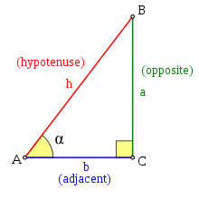
Figure 1: Sine Trigonometric Relation
Looking at the relation above, the length of the opposite side, a, is dependent on the angle alpha. If we assume that the hypotenuse, h, is a set length of 1, the length of a will increases as alpha increases and vice versa. This is the concept behind the Unit Circle, a way to visualize the way opposite side a change as alpha changes.
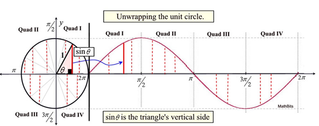
Figure 2: Sine Wave Unit Circle
As is shown in figure 2, as the value of the central angle changes, the value of sine will change as well, rising as the angle increases until the angle is 90 degrees. In this case, the opposing side will be equivalent to the hypotenuse, resulting in a value of one. Once this point has been passed, continuing to increase the angle will lower the sine value as we are now in quadrant 2 of the unit circle. Continuing to trace the value of the sine shows the value of sine as we pass through all 4 quadrants of the unit circle. This oscillation in the sine value as we traverse the unit circle is what produces the signature sine wave.
Sine Wave Generation Methods
Thus, considering this visualization of the sine wave from the unit circle, the method to generate the sine wave in firmware is essentially a mapping implementation. We must correspond an angular value and match that to a value point on the sine waveform. To achieve this, there are 2 basic methods.
Math Functionality
One method to generate a sine wave is by the provided math library. These libraries provide a plethora of useful functions to calculate common mathematical values. Sine is, of course, included in these libraries.
Pros
- Code Simplicity – Often, these library functions can be directly imported into code projects and then simply called. Provide the function with an input angle parameter and get the corresponding sine value which can then be used for whatever application is necessary.
- Memory Efficiency – As opposed to the sine table method, the math function does not require a large table to be stored in memory in order to calculate the correspondence between the input angle and the sine value.
- Granularity – Because the math function calculates the sine value in real-time when needed from the input angle, the resulting sine value has high precision, usually as much as can be provided by the algorithm used by the library in the calculation.
Cons
- Computation Speed – Since the sine value is mathematically calculated when the sine function is called, the time requirements for using the math table are much higher when compared to the sine table. Most sine functions use Taylor Expansion summations to compute the value of sine with high precision which requires many computations. Thus, whenever the sine function is called, time must be spent by the processor to compute the result.
- Library Reliance – Using the sine function requires the inclusion of a specific math library package in the project. This could affect code portability during development as a second machine may not have the library available, which requires another aspect of project management that is not necessary when using the sine table method.
Sine Table
The second method is the use of a sine table. This method creates an index table in memory, each entry corresponds a value of the sine input angle mapped to a precalculated sine value output. This table subdivides the 360 degrees or 2 pi radian circle value of the unit circle into equal parts and creates a sine table entry for each subdivision. This means that, for example, if a sine table were created for values of 1 degree, there would be 360 entries in the sine table.
Pros
- Functional Simplicity – Although a bit more work to set up and use, the sine table is functionally simpler to use than a math function. Since the sine table simply requires the use of accessing memory with an index, it is functionally equivalent to using an array. It does not require any complex mathematics or library calls.
- Computational Speed – Since a sine table is effectively a simple memory read, computing a sine value with a sine table is much faster than using a library math function.
Cons
- Memory Requirements – The sine table requires a table of values to the saved into memory. Based on the indexing values, this table could be of considerable size and place constraints on the availability of memory to other functions.
- Discreet Values – Because the sine table functions by relating an index angle value to a precalculated sine value, the resulting sine value can lack precision if the desired sine angle does not match one of the preset index values. This can be mitigated somewhat using linear interpolation between the two index values and the two output sine values. However, because sine waves are not linear functions, the results will still suffer a loss of precision.
Credits
Figure 1: Wikipedia – Sine : Sine - Wikipedia
Figure 2: MathBitsNotebook.com – Unit Circle and Trig Graphs : Unit Circle and Trig Graphs - MathBitsNotebook(A2 - CCSS Math)