The competitive nature of the upstream Oil & Gas industry perseveres even through downturn as evidenced by continued requests for more advanced technology. One trend we see at Erdos Miller is that continuous inclination measurement is evolving from a nice-to-have feature for advanced users and use cases, to an every-day requirement.
What is a continuous inclination and azimuth measurement?
A continuous inclination and azimuth (sometimes called inclination and azimuth while rotating) measurement attempts to calculate the inclination of the survey tool during the drilling operations. Yes, you read correctly: the tool takes an inclination measurement while the drilling operation is proceeding.
Typically, the rig will cease operations momentarily and allow the Bottom Hole Assembly (BHA) to settle (stop vibrating and rotating) in order for the survey instrument to attain an inclination measurement free of vibrational interference. While this is ideal from a quality of measurement stand point, it provides no insight into the progress made while drilling ahead.
Here is an analogy:
When you are driving down the road you keep your eyes open at all times, continuously surveying your position on the road and with respect to the position of other cars, and you make small adjustments as you go without interrupting your progress. You can think of the road as your planned well path and the other cars as other well bores you are trying to avoid. This is akin to what you can do while drilling with a continuous inclination and azimuth measurement.
Without continuous measurements, your driving experience would be something like this:
- Take a look at where you are and get an idea of how far and what direction you want to go.
- Then, close your eyes, hit the gas pedal and try to "feel" about how far and what direction you've gone.
- When you feel like you've gone far enough and no longer have a good feel for where you are or where you're going then stop the car, open your eyes and see where you are.
That's a little terrifying isn't it? I bet you would have a hard time staying on the road, and you probably would not be able to tell that you were too close to another car until you felt the unfriendly bump of a collision. This is akin to drilling today with static survey stations only.
Erdos Miller decided to develop a continuous inclination and azimuth algorithm about a year ago. We believed that it would be possible, using modern state estimation algorithms, to cut through the vibrational and rotational interference of the operating BHA and attain a measurement. Erdos Miller began designing an advanced algorithm that would allow us, within a reasonable margin of error, to calculate inclination and azimuth while drilling.
We took a three-step approach to delivering a commercial algorithm:
- Simulation
Initially Erdos Miller constructed digital simulations of a rotating survey instrument experiencing vibrational interference. We were able to extract semi-realistic outputs from the simulated accelerometers and magnetometers. We took care to simulate outputs which were non-ideal, including both vibrational and rotational interference, to ensure that our simulation output was as realistic as possible. We then took these simulated outputs and used them as a basis for designing our algorithm. The algorithm had to be capable of taking dynamic, non-ideal, interference-heavy measurements and quickly provide an accurate measurement of inclination and azimuth while the drilling operation progressed. Once we prototyped accurate measurements in our simulated model, we decided to take the next step.
- Lab Testing
Erdos Miller implemented the prototype algorithm on one of our MicroPulse tools. This allowed a good test bed with real sensors to prototype and evaluate our algorithm. We then went about constructing test equipment to evaluate our solution. During simulation, it was very straightforward to simulate simultaneous vibrational and rotational interference. However, in the lab this proved to be an order of magnitude more complicated. To simplify the problem, we split it in two. We used a standard vibration table to simulate vibrational interference and then we constructed an in-house "rotational stand" that we used to simulate rotational interference. Then we mounted the rotational stand to a roll-test stand provided by our friends at Digital Drilling Data Systems (DigiDrill.)
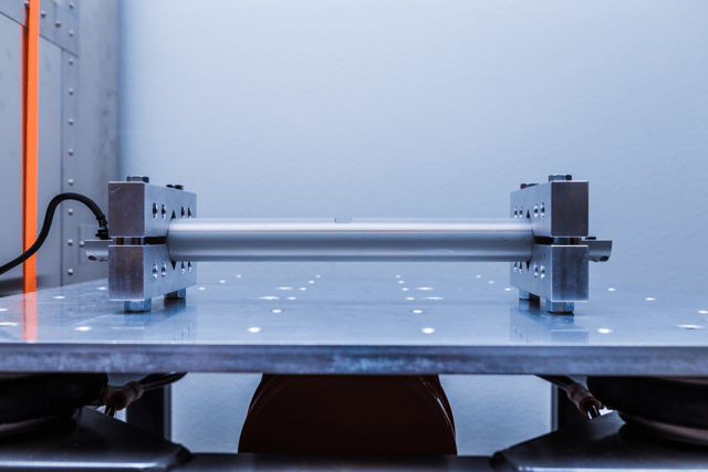
(Perspective 1 of the vibration table)
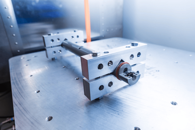
(Perspective 2 of the vibration table)
On the vibration stand we tested the algorithm at extreme angles. 0deg, 5deg, 85deg and 90deg. This allowed us to test the performance of the algorithm under vibration at extreme angles. Given the mechanical nature of the vibration table, it was difficult to test at other angles. On the rotational stand, however, we were able to test the algorithm at whatever directional heading we pleased at whatever RPM. We were able to test exhaustive combinations of angle and rotational speed until we were happy with the algorithm’s performance.
- Field Testing
The next step was to get our tools into an actual well bore and see our real-world performance. Even after all of our intense work in simulation and lab testing, when we got our initial results back from the field we were a little disappointed. Our measurements were not great, but they weren't bad either; we still had some work to do. We conducted dozens of field tests in different sections of the well, the verticals, the curves, the horizontals. What we found out is that our algorithm had to be tuned to operate a little differently in each of these hole sections. This was mostly due to how the magnetic and gravity fields were biased in the sensors as well as slightly different drilling practices in each hole section. We had to alter our algorithm to be intelligent enough to identify the hole section and setup itself up differently depending on where it was operating. Additionally, we learned there is a constant fight between responsiveness and accuracy. The more we attempted to make the algorithm accurate, the less responsive it became, the more responsive we made the algorithm, the less accurate it became. To solve this problem, we analyzed common rates of penetration and other behaviors in different well sections and further tuned the algorithm for the right amount of responsiveness and the right amount of accuracy in each hole section. For example, in the vertical, the algorithm needs to be more responsive due to sometimes seeing extreme rates of penetration. In the horizontal, accuracy is king as this is typically the part of the well where staying on path has the biggest payoffs in the long run. We worked hard and after several tests we had made some really great improvements to the algorithm.
Below you can see some of our initial results from one of our earliest runs in a Bakken lateral; the Image A below shows how the results were less than ideal. The dark green line below shows the static survey stations while the light green line represents the calculated Continuous Inclination and Azimuth measurements from our algorithm. The y-axis is the inclination angle and the x axis is time.
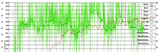
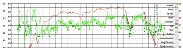
Image B, below, shows the much more accurate results after we further improved and tuned the algorithm.
It has been a long road but we feel it has been well worth it. The continuous inclination and azimuth algorithm is a tough puzzle to solve, but we feel that we are providing a great measurement that has real-world benefits to our customers. We will continue to refine our measurement into the future and believe that one day we will not have to stop for surveys at all.
Contact an Erdos Miller engineering expert today to find out how we can help you integrate our continuous inclination algorithm into your Measurement While Drilling (MWD) system.