In a previous blog post on the building blocks of an MWD system, I mentioned that one of the primary measurements that the system must make is the inclination of the tool. I also alluded to the use of accelerometers for said measurements, but I didn’t provide much detail beyond that. Since then, I’ve received thousands of emails basically just whining about how I didn’t write enough about accelerometers and about how they can be used to calculate inclination and several emails about how I can’t write good. Hurtful stuff, guys. And then there was that email about a deposed Nigerian Prince.
So, in an effort to redeem myself, I’ve decided to write a post that explains the basics behind what accelerometers are and how they can be used to calculate a tool’s inclination. But, let me be clear: I’m not doing this for the haters, I’m doing it for my new friend, Abiade, whose recent family situation, I have learned, has left him with a sizeable inventory of misplaced bullion. I feel like the realness of Ade’s turmoil is the only thing that can compare to hurtedness of my feelings from all the hate messages. Hang tight, buddy! Check’s in the mail!
This blog post will be divided into three parts: In the first part, we’ll try to keep things as simple as possible and attempt to give a good intuitive understanding that will be helpful moving into the second part; in the second part, we’ll begin getting into the mathematics behind calculating single-axis inclination from accelerometer readings; finally, in the third part, we’ll continue developing the math for a three-axis application in MWD.
The Basic Concepts
Recall that inclination is one of the primary ways of describing an object’s orientation and that it is a way of quantifying how tilted the object is. Since we live in a three-dimensional world, there are three different directions that an object could be tilted (see the picture below, I stole it from Analog Devices). For some applications, there may only be one or two directions that are of interest, however, in MWD, we care about all three directions (in the picture below, the three directions are labeled as +X, +Y, and +Z).
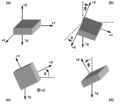
Figure 1 - Picture I taken from Analog Devices
So, if inclination describes how tilted an object is, how does it make sense to use an accelerometer to measure inclination? After all, an accelerometer measures acceleration, i.e. how fast is the speed of an object changing? The answer to this question is one of Isaac Newton’s most famous inventions: Gravity. (Disclosure: I am not an expert on gravity or on inventions). This answer might come as a surprise because we usually think of acceleration as that exhilarating sensation we get when a car or roller coaster speeds up real fast – we usually don’t think of it as the thing that caused that apple to demolish Isaac Newton’s head (I’m also not an expert on Isaac Newton).
As it turns out, gravity is one of the most useful types of acceleration for engineers because it’s all over the place and, if we’re limiting our discussion to Planet Earth, it’s the same everywhere! Gravity is the same everywhere in the sense that it has the same magnitude (9.81 m/s2 or 1 g) and the same direction (perpendicular to the surface of the earth and, by convention, pointing towards the center of the earth) regardless of location on the earth. (Strictly speaking, it’s not 100% true that gravity is the same everywhere, but, for most practical purposes, it’s close enough to true as makes no difference.)
Since gravity is a constant acceleration, we can use an accelerometer to take advantage of its non-changing qualities and, with a little bit of math, calculate inclination. However, like I mentioned earlier, we’re going to hold off on the math for now and just try to develop an intuitive understanding of what’s going on.
For our intuitive explanation, imagine a piece of paper with a square cut out of its center and imagine that that piece of paper is being held above and parallel to a dark surface. When light shines straight down from above the piece of paper, there should be a square of light that is projected onto the surface. In this analogy, the piece of paper is the accelerometer, the light is gravity, and the projection of light onto the surface is the measurement reported by the accelerometer.
When the piece of paper is tilted along one of its axes, the corresponding edge on the square of light will be compressed; if it’s tilted along its other axis, then the other edge will be compressed. If the piece of paper is rotated, then so too will the light projection. Regardless of the piece of paper’s configuration, the light (acceleration due to gravity) remains the same.
The principle that enables inclination to be calculated from accelerometer measurements can be summarized as follows: Based on what we know about the light (constant direction and magnitude) and based on what we know about the piece of paper (shape of the cutout), we can determine the inclination of the piece of paper just by looking at the projection of light on the surface.
There are a few nuances with the paper-cutout-light analogy that also apply to accelerometers. One of those nuances has to do with the idea of a ‘sensitive axis.’ In the analogy, we could detect a rotation in any of the three direction – in two of the directions, the light projection would become a rectangle and, in the third direction (spinning the paper clockwise or counterclockwise), it would become a rotated square. An accelerometer that can detect a rotation in all three axes is said to be a 3-axis accelerometer. However, imagine if, instead of a square cutout, the piece of paper had a circle cutout: Tilting the piece of paper from side to side would result in oval light projections, but spinning the paper would still just result in a circle light projection. In this case, information can only be collected for two of the axes (these are said to be the ‘sensitive axes’).
As it turns out, there are accelerometers that are sensitive in only two axes. As a matter of fact, there are even single-axis accelerometers (think of a long, skinny strip cutout from our piece of paper – we would really only be able to see the light projection get shorter and longer as the paper tilts along its single sensitive axis).
There are other nuances in our analogy that also apply to accelerometers. For example, the perceived shape of the light projection depends on things such as the distance between the piece of paper and the dark surface: If the piece of paper is far from the surface, the light projection may begin to appear blurry and, if the paper is too far, the projection may so blurry that it becomes impossible to determine any meaningful information about the inclination of the paper. There is a real-life analog of this phenomenon in the context of accelerometers, however, it will be easier to discuss that after we get into the nitty-gritties in Part 2.

Inside this whitepaper you will find:
The CAN Frame Structure
Everything you need to know about Message Formats
Command structure
Common commands for all tools, and more!