What is the SCPI Protocol?
Released by Hewlett Packard in 1990, Standard Commands for Programmable Instruments, SCPI, is an additional layer positioned on top of the the '.2' revision of the 8-bit parallel multi-master interface bus specification, IEEE-488. Dictated by SCPI are a common syntax, command structure, data format, and generic commands across all instruments that adhere to the protocol. There are also sets of generic commands based on the type of instrument being interfaced. The protocol is also able to be used with most buses available today including GPIB, Ethernet, and USB. SCPI is available on almost every piece of electrical laboratory and industrial hardware available today. Knowing how to operate on SCPI is an indispensable asset to anyone working with such equipment.
SCPI Interfacing
How exactly do we tell the instrument what we want it to do? SCPI commands are sent to devices as ASCII strings. Two types of operations can be sent to instruments: SET and QUERY operations. Set operations change the configuration or parameters of instruments such as setting our RIGOL M300 to measure resistance. Query commands return data after the sent command is executed and can be used to set instrument configurations at the same time. Query commands are typically sent with a question mark at the end of the ASCII string.
Set vs Query
For example, say that an instrument has been set to measure DC voltage through a set command. We can now query the instrument and get it to send over the data from its output buffer. What if we now want to get the amount of current flowing through our circuit? Instead of sending a set command, we send a query command to measure current and immediately have the instrument return the data that entered its output buffer as a result of the measurement.
Command Syntax
So just how is the SCPI command structure oriented? SCPI commands are ordered in a hierarchical structure and related commands are then grouped into subsystems.
The first layer of commands is composed of general commands. General commands are available between all instruments supporting the protocol. Examples are '*RST', *SAV, and *RCL; Reset, Save, and Recall respectively. The second layer contains standardized subsystem commands such as MEASure, READ?, ROUTe, and SYSTem. After the second layer, the amount of layers and available commands varies depending on the manufacturer of the device.
Below is an example of SCPI command notation from the RIGOL M300 Programming Manual:
CONFigure:RESistance [{<range>|AUTO|MIN|MAX|DEF}[,{|MIN|MAX|DEF}],](@)
This query command could be sent as “CONF:RES AUTO, DEF, (@101)”. Let's break down what the command is trying to tell us:
- The capitalized letters in the first words of the command let us know that we can send only those letters instead of the whole word to get the same result. 'CONFigure:RESistance' becomes 'CONF:RES' and achieves the same effect.
- The curly braces, {}, state that parameters notated within the braces must be selected and sent as part of the command. Our command wants two parameters to be sent with its command.
- The vertical bars, | , state that the words separated by it are interchangeable commands for that part of the whole command. For the first parameter, we can select AUTO, MIN, MAX, or DEF.
- Square brackets, [] , state that the keywords in between them can be omitted as part of the command. It's not necessary to send either of our parameters because they are both inside square brackets.
- Triangle brackets, <> , specify that a value must be given at the point in the command. Here we can choose to specify a range, one of the other commands, or not specify anything since our parameters are enclosed by square brackets outside of the triangle brackets.
- The '(@)' is specific to the RIGOL M300 and is used to tell the M300 what it is supposed to be measuring the resistance of. In this case, it will measure at slot 1 on the channel '01', hence @101.

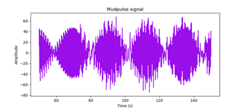
A Practical Usage of SCPI: Ring Out Testing with the RIGOL M300
Ring Out Testing
Ring Out testing is when each pin of a connector on one side of the tool is tested against all other pins of the tool. The goal is to acquire and record a resistance measurement between every possible circuit through the tool. This test allows us to electrically verify that all wiring and components on the tool are properly oriented. The values of all resistance measurements are verified against a known set of measurements. Potentially catastrophic issues can be easily avoided by adding this method of testing to the build process of any electrical device.
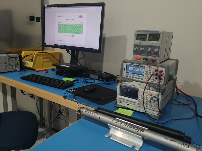
As part of the MicroPulse build process, for example, a ring out test is performed before a tool is powered. To accomplish the goal of ring out testing MicroPulses with the RIGOL M300 Data Acquisition and Switch System, the following circuit was constructed:
The Circuit
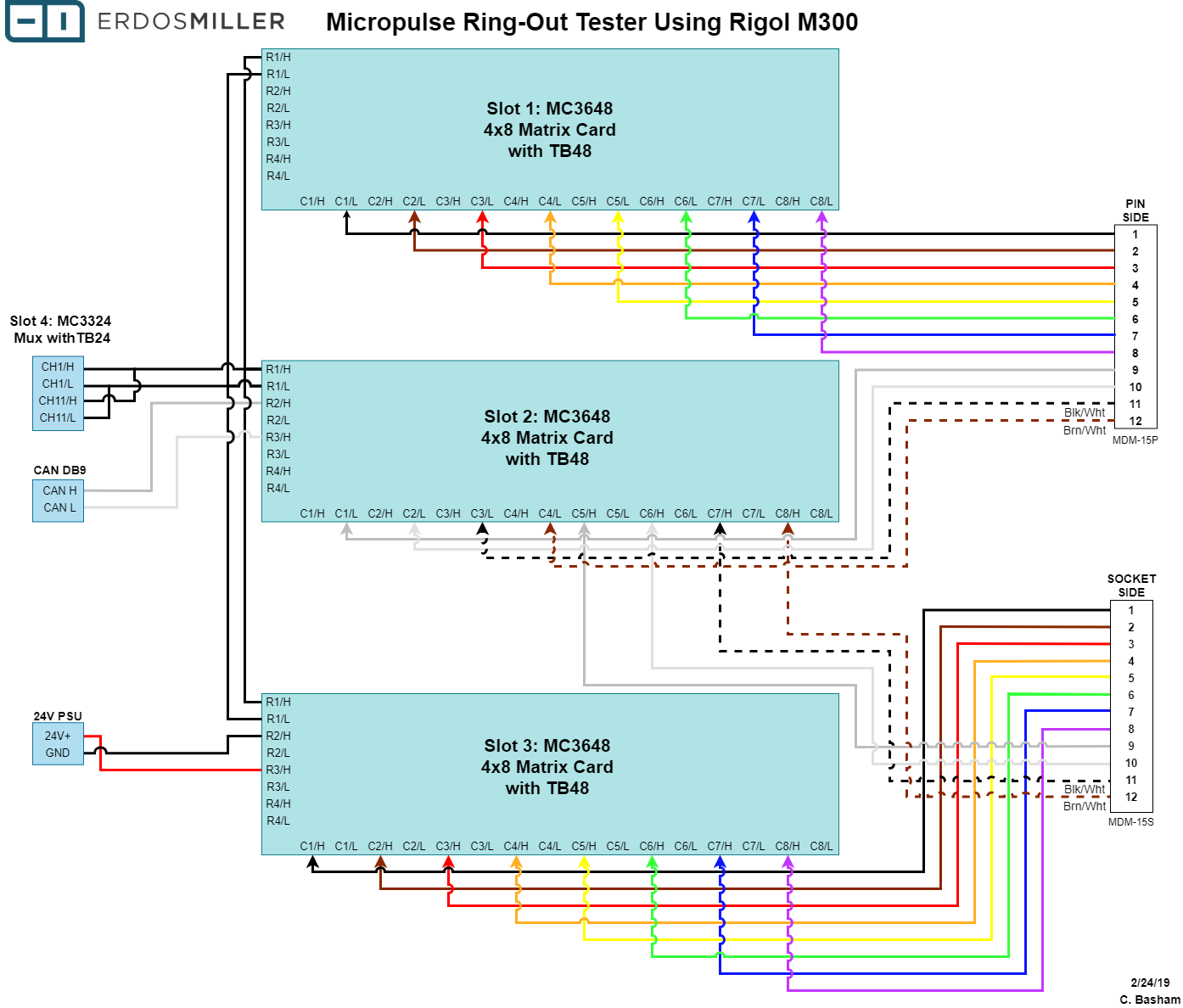
Pictured are three 4 x 8 matrix cards with the respective high and low sides of row 1 of each card connected and then to the respective high and low sides of channel 1 of the multiplexing card. Each matrix card can connect any column to any row of that card, connecting both the high and low lines in the process. Connecting the rows allows continuity across multiple cards. The measurement between the high and low lines of our row 1 bus line is made at the multiplexing card in slot 4. We will be using a four-wire resistance mode so the respective high and low lines of channel 11 are also connected to channel 1's high and low lines. We are so able to power the tool and communicate via can using some additional inputs that are beyond the scope of this article.
The Procedure
The main goal here is to utilize the M300 and Python to run a full ring-out test and output the result in a matrix. Python will open communications with and then direct the M300 to: connect whatever pins are specified, take a measurement, disconnect the previously connected pins, and close communications. This pattern will be performed until every pin of the MDM connector on one side has been tested against all of the pins of the other side while building a list of lists containing values for each measurement.
Interfacing SCPI with Python and the VISA Library
In order to interface through SCPI with Python, the PyVISA library must be installed. To install with PIP, enter 'pip install -U pyvisa' into Terminal/Command Prompt or, for more information open the previous link.
In addition, National Instrument's NI-VISA library is also required and can be downloaded here.
That's all we need to get started, other than connecting the instrument to be used via USB, GPIB, or Ethernet. Let's get started.
Programming
Let's get started: Pull up your favorite coding music and settle in.
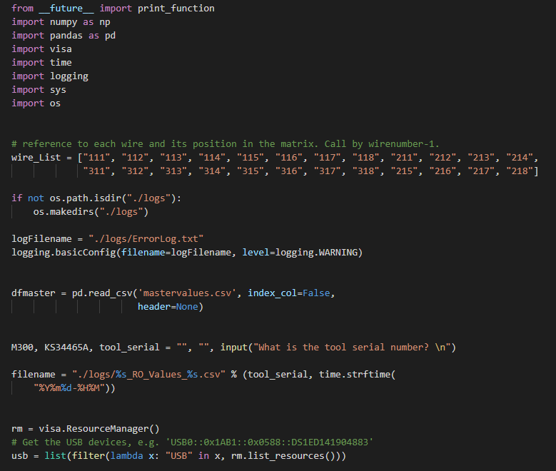
I've pared this down to be as simple as possible for explanatory purposes. We will be writing the information to a Pandas dataframe, taking a median for retries with Numpy, using the Visa library, timing the execution with Time, logging any errors with Logging while specifying a logs folder with OS, and using a few workarounds to print out data in a visually appealing manner in Python 2 hence the inclusion of __future__ and SYS.
First, we hard-code our wire reference numbers for the M300 for use later. We create a logs file and folder. We read in our reference values from 'mastervalues.csv', set a few working variables, and set an output filename. Next, we call visa.ResourceManager to get all of the devices available to use in the rm variable. We then filter that list to only include devices on USB since that is our chosen bus.
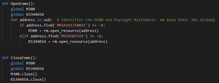
These two functions are for opening and closing communications with the devices we are using. We are using a Keysight digital multimeter and an M300 here but this is also a good example of how to use multiple SCPI enabled devices in tandem.
Since we know the addresses of the devices already we can search the list 'usb' for those and set our two device objects in that manner. Once have those object we can close our communications with the .close() command.
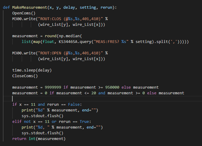
Here is the measurement function: It opens communications to the M300 and closes the appropriate parts of the matrix cards according to our aforementioned wire lists through index references.
A command to connect Pin 2 to Socket 2 would be “ROUT:CLOSE (@121,321)” meaning that for slot 1, column 2 would close onto row 1 and for slot 3, column 2 would close onto row 1. In this case Slot 4 where the DMM enabled multiplexer is located, closes channel 1 and channel 10 so that a Fluke multimeter can be watched for overall verification purposes.
We then ask the Keysight to measure the circuit and write the result to the measurement variable. You could really just round the query itself but this line also works for another method I'm working on, so I left it as-is.
We then delay for .03 seconds and close communications.
The last part prints the results in an aesthetically useful format and returns the measurement as an integer instead of a float.
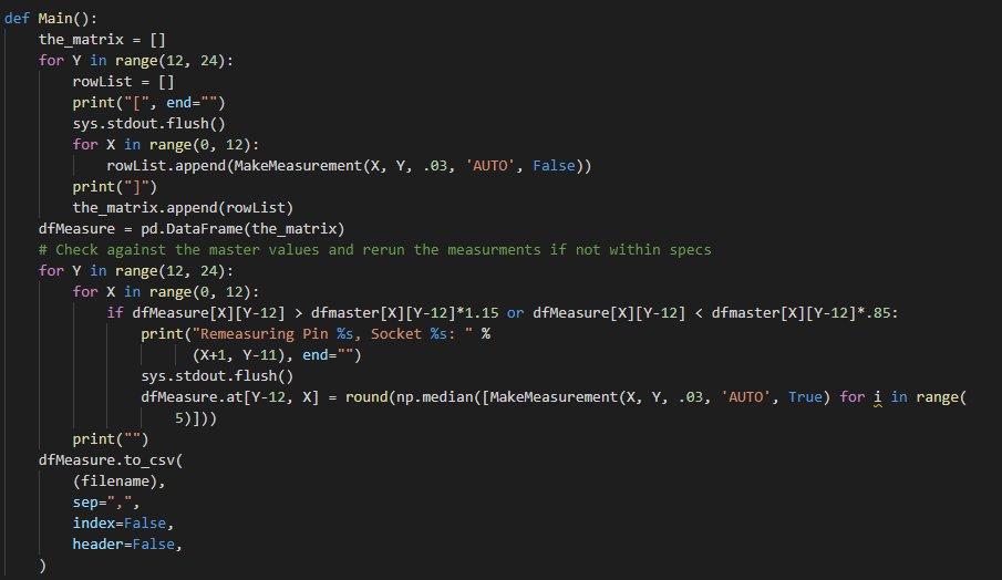
This is the meat of the program: We build an empty list to contain our lists of measurements and then begin iterating over our pins, starting with 12 for list indexing purposes and start our real-time list output with a print command and flush it to prevent new lines.
We then iterate from our first pin through the opposing 12 starting with index 0. We make our measurement and append the returned number to our list for this row.
After the first loop completes, we check the dataframe we made from our lists of lists and verify it against our known resistance values. If one value does not meet specifications then we run the measurement command five times and take the median of the measurements. The results are written to a csv in the end.
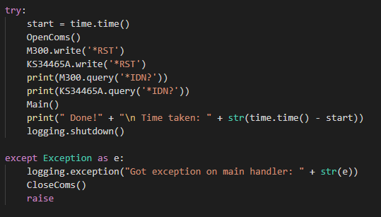
This is the main execution loop: We start our timer, open our comms, reset both devices to their default states, and ask them for their addresses to verify they're there. We run our main function, print how long it took to run the test and close out our logging before we are done. That's ring out testing in 122 lines.
We do a little bit more than that and generate a PDF showing the results and a pass/fail. We also get some information from the tool.
If you've read this far, high five; You deserve it. This has been a demonstration of the SCPI command interface and a practical guide to using it. I hope that you have been enabled to do more by taking the time to read this.