After dozens of hours designing an assembly and weeks of waiting for parts to arrive, it’s a terrible feeling when you finally try and put the parts together and something doesn’t fit right. When designing parts, it’s easy to be so worried on whether or not the parts can take the stress, fatigue, torque, and so on, that you forget to think about how somebody will actually put the parts together. Adding small details to tools during the designing phase could save hours of time (and swearing) during the assembly phase.
Here are a few tips to consider when designing parts that will make assembly easier:
- For parts with a tight fit, leave a gap of .005”-.010”. For parts with a loose fit, leave a space of >.030”.
Some parts should have a tight fit, and when assembling should feel like they are ‘perfectly’ fitting into one another. That perfect fit isn’t a line-to-line fit where the parts are actually touching, but one where air can easily escape and tolerances won’t be a problem. A gap of around .005” is the diameter of a couple strands of hair and looks invisible from afar, but the absence of that gap is extremely noticeable when trying to fit two parts together.
(Note that usually tolerances for parts are +/- .005”, so be sure that you design the tolerances such that the minimum gap is .005”)
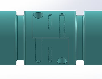
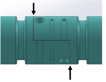
The joint on the left has such a tight fit that any offset in the mounting will make them incredibly hard, if not impossible, to put together. The joint on the right has .010” gaps that allow for movement.
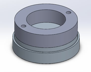
- Only 2 locating pins are needed to prevent two parts from rotating. Adding more locating pins doesn’t provide any benefit, it just makes it a harder fit.
Locating pins are anti-rotation devices and are useful for orientating, or clocking, parts to one another. However, only 2 dowel pins are required to prevent parts from rotating. Adding more locating pins won’t make the parts rotate any less, they just increase the chance that one pin or hole will be misaligned and prevent the parts from mating.
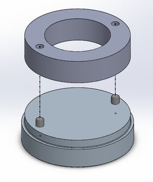
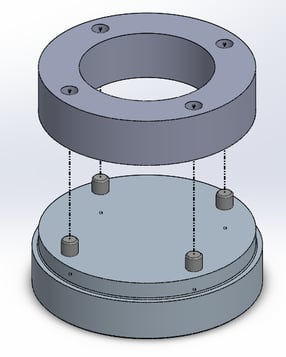
The ring on the left can’t rotate once it’s on top of the dowel pins. The ring on the right also can’t rotate but requires for 4 pins to be precisely placed instead of 2. If one of those pins is off, the parts can’t mate and are unusable.
- When sealing a rod in a shaft, the threads should engage before the O-ring. Otherwise you’re pushing in the O-ring and twisting against it trying to get the thread to start.
For sealing rods, you want the threads to catch before the O-ring engages so that as you screw in the part the thread is helping you pull the O-ring into the groove. If the O-ring engages before the thread, then you must push in the O-ring (which can be difficult) and then try and turn the part against the O-ring friction to try and find the thread.
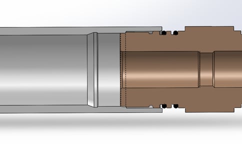
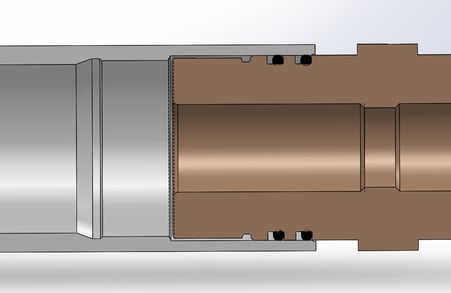
The left version shows the connection threading in before the O-rings touch. The connection on the right needs to be pushed in and spun against the O-rings to try and find the thread.
- Try and use common screws (UNC, with lengths of 1/8” increments)
There are countless screw types and thread forms available, but for your application you should stick to common coarse threads if possible. Coarse threads are simpler to work with and they thread in with fewer turns, saving time if you have to screw in dozens of fasteners. If you can’t use coarse threads because you’re relying on the 1 or 2 extra turns from a finer thread to ensure you have good purchase, then it’s better to revise the part to add more material. (You should have at least 4.5 turns of engagement as a rule of thumb)
Also, try and use the same length of screw consistently throughout your tool for each thread size. For example, if you’re using both #4-40 and #6-32 screws then try and have all of the #4-40 threads be of one length and all of the #6-32 threads be of one length. This dramatically decreases the amount of time that technicians need to spend hunting for screws and helps prevent mix-ups. I would also recommend that your screw lengths use 1/8” increments for UNC threads rather than 1/16” or 1/32”.
- If two parts are completely flush when mated, add spots for fingers or tools to go.
Assembled tools will usually need to be disassembled eventually, and when two smooth surfaces mate on both their faces and outside edges they can be extremely difficult to pull apart. (Just think back to how difficult Lego pieces are to take apart once they’re tightly pressed together.) To overcome this, add in grooves where you can fit your fingers or a tool to pry parts apart.
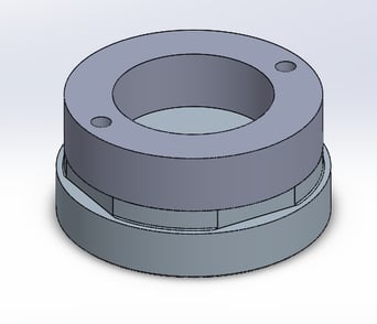
Going back to the ring example, if those dowel pins are tight then getting the ring off the left assembly will be difficult. The slots on the right give a tool leverage to pry the ring off.
- Try not to use O-rings that are within 3 sizes of each other, and always design O-ring grooves to the Parker standard.
Like your screws, you don’t want your O-ring sizes to be so similar that somebody could accidentally use the wrong one. For instance, if you use a size 2-218 O-ring throughout the tool, there shouldn’t be one spot where a size 2-219 is needed. It’s very probable that eventually a 2-218 O-ring would go in the 2-219 groove, be overstretched, and fail.
Generally, O-rings can be forced to fit in grooves two sizes larger or two sizes smaller. By designing grooves that are further away in size, the O-ring will be obviously too loose or too tight when someone is trying to put it on.
Also, when designing O-ring grooves always design to the Parker standard (found here, page 4-5). The common O-ring sizes don’t cover every combination of ID/OD, so trying to add in a groove after you’ve finalized other features could be impossible without specialty, expensive O-rings.
- Add a radius or chamfer to any edge where a part needs to pass.
Finally, here’s the most basic and fundamental tip to consider when designing for assembly. Don’t forget!