Finite Element Analysis (FEA) can seem like magic when you first use it. The program does all the hard math for you for any complex shape and for any type of loading. Just put in the right ingredients, and the program practically designs the part for you.
The problem with FEA is the same as with programming: Garbage In = Garbage Out. The program does exactly what you tell it to, so if you set it up incorrectly then you’ll get useless results.
For downhole parts, the most common analyses used are Structural, Thermal, and Modal. Computational Fluid Dynamics (CFD) is also commonly used, but generally uses completely different software packages. For general design work and part iteration, structural analysis is the most common, so here are some tips for properly setting up structural FEA. I’m focusing on static analyses here, so this doesn’t consider dynamic cases where the load changes over time.
Setup
- Turn on Large Displacement
With large displacement on, the analysis applies the static load in steps so that the part can bend realistically under loading. If it’s off, the load is applied in one large step which leads to inaccuracies. Most programs will warn you if they detect significant enough deflection to warrant large displacement, but the option should just be turned on at the start.
- Try to run 2D before 3D, or run a half-model or quarter-model
One thing you will quickly learn about FEA is that it’s very time consuming. Setting up the model takes time, setting up the analysis takes time, and running the analysis takes even more time. To quickly iterate on a design, use a 2D cross-section or axisymmetric model. For example, a 2D analysis of a single part can run in less than 5 minutes, or less than 1 minute in some cases, whereas a 3D analysis of the same part would take 15+ minutes. If a 2D cross section isn’t realistic, try using a half- or quarter-model cross section with frictionless boundaries where the halves or quarters would meet.
- Defeature parts before importing them
There are a lot of features that introduce complicated geometry into a part that won’t have any bearing on the result. If a hole, chamfer, radius, or other feature is far away from the stress, then remove it. For example, engraved letters usually don’t have any bearing on an analysis and could be removed to speed up run times.
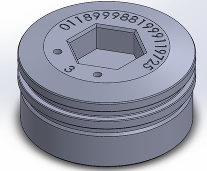
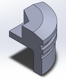

Modeled part vs. quarter section vs. 2D. The defeatured quarter section and 2D section will solve much, much faster.
Material Properties
- Use minimum accepted yield for the part you are making
Don’t just look up whatever material you are using on Google and then use the first listed yield strength. There are a huge range of possible strengths for materials based on cold working, age hardening, and more. Use whatever the drawing or your reference material states are the minimum accepted yield and ultimate strengths for the specific material.
- Use the material properties at temperature
Further, material properties change with temperature. Particularly, the yield and ultimate strengths degrade as the temperature increases. To find out how much materials will degrade, look for technical specifications from the manufacturer or look for research papers. One good resource for common metals is military specification MIL-HDBK-5J. Always run your analysis at the maximum rated temperature to design for the worst case.
- For nonlinear analysis, you need to define the material stress-strain curve
Nonlinear analyses are much more accurate than linear ones as you begin to approach yield, but the pain is that you need to properly set up the material properties. To get a proper stress-strain curve, you’ll need define each point along the curve for the analysis software. The simplest way to do this is to find an existing stress-strain curve and manually use a ruler and pencil to note each point, but the proper method involves more legwork in generating a curve from known properties.
Meshing
- Have at least 4 mesh elements across each thickness
With meshing, it’s sometimes difficult to know when you’ve gone far enough. A good rule of thumb is to set the element size small enough to have at least four mesh elements across the smallest thickness. This will usually be a smaller element size than whatever the ‘fine’ setting is on the default slider.
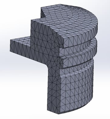
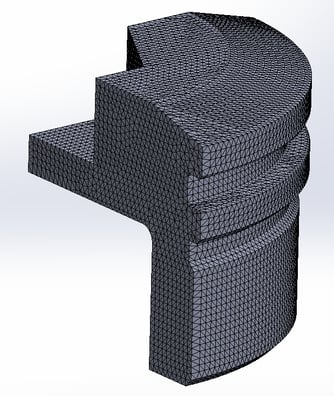
The left is too coarse. The right mesh has at least 4 elements across the minimum thickness.
- Use local mesh controls to increase density in studied areas
Some FEA software can decrease the mesh size only in certain areas. I know that in ANSYS this is called the ‘pinball’ region. Creating these regions around the area that you want to study can dramatically reduce your run time compared to trying to increase the mesh density across the entire assembly.
Loading
- Use the maximum expected load conditions, and then check beyond.
This should go without saying, but if you’re spending all the time to set up an analysis to check if a part will fail or not, don’t bother with anything below the maximum. Then, check beyond the expected load to what you imagine the next revision of the part would try and support. For example, if the part will be rated to 15ksi of pressure, run the FEA at both 15ksi and 20ksi. Running it at higher loads could show the weak points more clearly and will give a better indication of the safety factor.
Results
Properly viewing the results is one of the most overlooked parts of running FEA. It is very easy to mislead yourself with information-dense results after you’ve put all the effort in to setting up the analysis and to skim the material and quickly decide that you’re done and that the part is good. Also, it’s very easy to mislead other members of your team with pretty pictures if they don’t know what to look for – nobody wants to stop the very impressive looking, colorful presentation to complain about units on the legend.
- For stress, set ‘red’ as anything beyond the yield strength of the material for stress
People expect for ‘red’ to mean ‘bad’. The software will automatically assign red as the maximum stress in the simulation, not as the yield strength. Make sure to change the legend and to keep it consistent across analyses.
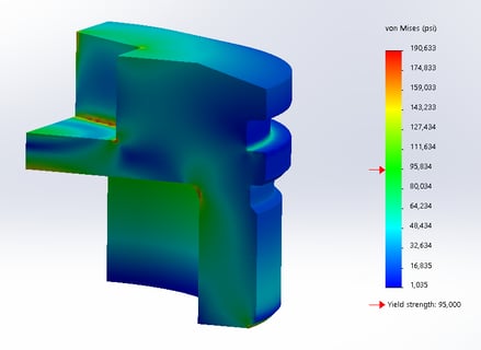
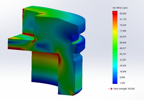
Automatic Colors vs. Yield as Red. The left part looks 'good' to most people. The right picture shows the trouble spots much more clearly.
- For strain, set ‘red’ as 0.002 for elastic strain to indicate plastic strain
0.2% elastic strain is the common yield point for metals. If the results show the part going beyond this, then you should switch to a nonlinear analysis if you haven’t already.
- When taking screenshots, make sure the legend is extremely visible with large, readable text and numbers
This is a common problem for most presentations. The legend is what makes sense of the pictures you show, so make sure that’s is visible from across a room when presented.
- Don’t just rely on Von Mises stress. Check the 1st and 3rd principal stresses.
Von Mises stress can present a false picture of the results. Because it averages all the stresses into one result, offsetting stresses can cancel each other out. To see the true picture, look at the 1st principal stress to find the maximum tensile stress and at the 3rd principal stress to find the maximum compressive stress.
Double and Triple check everything before accepting a result.
After spending hours setting up and running an analysis, it’s very tempting sometimes to accept any good result to quickly move on to the next project. FEA takes time to do right and there’s a lot that can go wrong. Double check each step listed out above: the setup, the material properties, the loading, the mesh, and the results. Having just one part wrong will invalidate your entire result. Do it right the first time, and save yourself the time!