Three Building Blocks of an MWD System
There is often a point early in the learning process where the student knows so little of the subject that they don’t even know what questions to ask. Imagine trying to teach someone who has no concept of a car (like a road cyclist) how to drive – words like ‘apply gas’ and ‘press the clutch’ and ‘you need to stay in your lane’ would have very little meaning to them because they don’t have a frame of reference for those things. Instead, the initial description might need to look something like this:
The purpose of a car is to take its passengers from one location to another. Here’s how a car works: It has four roundy wheelies to roll around on; it has an energy block (sometimes gas type and other times electric type) that makes the wheelies go round; and it has foot buttons and a turning circle that allow the driver to go forward, stop going forward, go left, and go right.
My description of a car is what some people might call a ‘gross oversimplification’ and possibly even ‘borderline condescending’. Those people would be correct. However, for someone who has no idea of what a car is, a bare-bones description like that could serve as a good primer. Nobody is going to argue that even the simplest car is orders of magnitude more complicated than what I’ve described, but the objective here is not to give technical discourse or even to answer very many questions – the objective is to give road cyclists just enough information so that they can begin asking questions and start self-navigating their learning journey.
In the same vein, the purpose of this post is not to delve into the technicals of a Measurement While Drilling (MWD) system, but to give a very high-level overview to people who have had very little to no exposure to one of the oil and gas industry’s biggest ballers. Just like with my car example above, most of what follows will be very hand-wavy and very non-technical, hopefully not to the point where it comes off as condescending.
Introduction
During a drilling job, the machine operators in charge of steering the tool need to know certain things about their current position in order to make informed decisions in moving forward. Typically, this includes the wellbore’s (the hole’s) current angle of inclination as well as what direction it’s pointing relative to north. The building block of the MWD system that is responsible for taking these measurements is the Inertial Measurement Unit (IMU), which is in the wellbore. Once the measurements have been taken, the information needs to be encoded and sent up to the surface – this is the Telemetry building block. Finally, at the surface, the Surface System is used to decode and display the information that was transmitted by the IMU.
Inertial Measurement Unit – “The MWD”
“Inertial Measurement Unit (IMU)” is a general term for electronics that use sensors to calculate position and orientation. Pretty much all modern vehicles, from cars to airplanes, have some sort of IMU. In oil and gas, given that the IMU is the “M” in “MWD,” industry sometimes refers to this building block simply as “The MWD.”
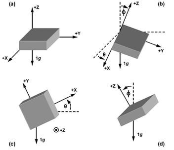
Two of the primary measurements the MWD is responsible for are inclination and azimuth: Inclination is the angle of the wellbore with respect to vertical and azimuth is the angle of the wellbore’s direction with respect to North. The figures below help illustrate what these measurements look like: Inclination is simply a way of quantifying how vertical the wellbore is at a given point and azimuth is a way of describing what direction the wellbore is pointing.
When the wellbore is completely vertical, the inclination is 0° and the azimuth is undefined. When the wellbore takes a turn, the inclination begins changing from zero and, for most drilling operations, may eventually end up at 90° (horizontal). Additionally, when it changes direction from vertical, the azimuth describes that direction: If it is going North, the azimuth is 0°, if it is going East, the azimuth is 90°, etc.
Accelerometers and magnetometers are the bread and butter of the MWD. Together, these sensors can be used to measure inclination and azimuth (there are conditions when these sensors are not enough, but that deserves more attention than I’m willing to give here). Once the measurements have been taken, the MWD needs to transmit the data to the surface, where it can be interpreted by rig operators.
Telemetry
There are two primary methods for communicating information from down-hole to the surface: They include mud-pulse telemetry and electromagnetic (EM) telemetry. Both these methods have their pros and cons and various implementation challenges, however, for sake of brevity (remember, this is just a primer), only their basic theory of operation will be discussed. And I’m talking Pumpkin Spice Latte Basic (PSLB).
Mud-Pulse Telemetry. During drilling, a special kind of mud (drilling fluid) is pumped down the tubing and then sent back to the surface. Electronics at the bottom of the hole drive a valve that can constrict and relax the flow of this mud, creating pressure pulses in the fluid that’s circulating in and out of the hole. These pressure pulses are the heart of mud-pulse telemetry (more on what happens with these pulses later).
EM Telemetry. Most people don’t usually think of the earth as being a conductor and might be surprised to find out that it is. Maybe not as good of a conductor as a piece of copper, but a conductor, nonetheless. At any rate, the earth’s conductive properties can be taken advantage of for data transmissions. If you have some special electronics known as an ‘EM Transmitter’ at the bottom of the hole, you could stick two probes in the rock and send a sinusoidal signal through the earth, up to the surface (more on what happens with these signals later).
Typically, only one of these methods are implemented at a given time. It’s important to know which one is being used, because the surface system needs to know what type of signal it should be expecting (If you designed an MWD system with an EM transmitter and a mud-pulse surface system, you would be pretty embarrassed! Haha, you might even be fired!)
Surface System
The purpose of the surface system is to receive the data transmitted from downhole and to display that information in a way that is meaningful to the rig operators. If the method of telemetry is mud-pulse, the surface system will include a pressure transducer that detects the pressure pulses in the drill fluid and converts the pulses to electrical signals; electronics are designed to convert these electrical signals into ones and zeros. If the MWD at the bottom of the hole did its job right, the ones and zeros received at the surface will be able to be decoded and give meaningful information.
In the case of EM Telemetry, electronics are designed to detect the sinusoidal signal that was transmitted from the bottom of the wellbore. The challenge with this is that, by the time the signal travels from the bottom of the hole to the surface, it will have lost most of its power to the earth and the electronics need to be able to amplify it in a way that it can be identified amidst the noise that will inevitably creep in. Like mud-pulse telemetry, the EM transmitter is responsible for encoding data into the signals that are transmitted and, when those signals are received at the surface, they will be able to be decoded and give meaningful information.
For either mud-pulse or EM telemetry, once ones and zeros are received, they are sent to a special computer called a Rig Floor Display (RFD), where the information is decoded and displayed. RFD’s are special because of the way that they are (again, I invoke PSLB to justify this appalling explanation). The rig operators can then use information (such as, but not limited to, inclination and azimuth) to make decisions on how to move forward in their drilling operations.
The three building blocks of an MWD system encompass the getting of information, the transmitting of information, and the receiving of information. The success of any drilling operation relies on these blocks to function seamlessly, both independently as well as with each other. This post did not provide a lot of details on how that is accomplished, but, hopefully, it did provide enough information to outline some of the major objectives in designing electronics for oil and gas – and, when you’re learning to drive, it helps to know what a car is!