Any large application needs a method of organizing and accessing functionality and data. This method is known as an architecture. There are many possible architectures available to developers. Some architectures are specific to LabVIEW while others are more general and can be adapted to any programming language.
The Model/View/View-Model or MVVM architecture is based on the Microsoft architecture used for Windows Presentation Foundation (WPF) and Silverlight applications that provides support for XAML user interfaces with two-way data binding.

Figure 1 - MVVM Architecture
MVVM can be implemented in LabVIEW to provide a light-weight architecture that:
- Improves code re-usability
- Maintains a short learning curve
- Provides for easier source control management.
The MVVM architecture consist of three major components:
- Model – the data model representing all the private and public data for each module
- View Model – responsible for providing Views with the latest data stored in the Model as well as updating the data model in response to external actions
- View – a user interface for displaying the Model and providing input to the Model
The MVVM architecture implements multiple asynchronous modules that maintain their own Model in the form of a Data Value Reference (DVR) as well as their own View-Model in the form of user events for data binding.
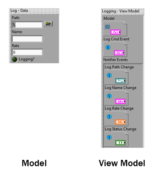
Figure 2 - LabVIEW Model and View Model
In an MVVM architecture, the Model is simply a cluster of varying data types specific to a module. In Figure 2, the model for a logging module is defined. This Model contains a path to the log file, a log name, the logging rate, and the log status.
In the example image on the right, the logging module’s View Model is defined. A View Model consists of a data value reference containing the Model data, a command event, and an individual notification event for each variable in the model.
The command event provides an Application Programming Interface (API) that allows other modules to communicate with the logging module. Likewise, the notification events allow other modules to bind to the logging module’s Model.
After defining View Models for each module, all View Models are bundled into a single cluster known as the “View Models” type definition.
A typical MVVM Main VI is shown in Figure 3. At the start of the program, all of the View Model references for each module are generated and bundled together in the View Models type definition. This type definition is passed to all of the modules in the application. This provides global access to event references for data binding as well as command events for inter-module communication.
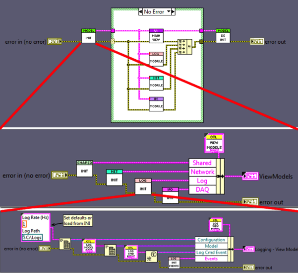
Figure 3 - Main VI
A typical module architecture looks like Figure 4:
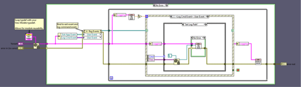
Figure 4 - Logging Module
The module first casts a variant to the project’s View Models type definition. This cast allows the module to be reusable across multiple projects containing different View Models type definitions. Simply replace the View Models type definition with the one specific to your project.
Once the cast is complete, the module should register for its own command event as well as any notification events it may need (in Figure 4 the logging module also registers for an application exit event).
Each module is responsible for maintaining its own Model and notifying other modules and Views of updates to its Model. To do this, several accessor VIs should be developed.
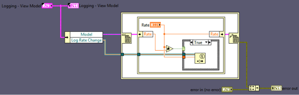
Figure 5 - Rate Accessor VI
Figure 5 demonstrates how to update the rate variable in the logging module’s Model. Use in place element structures to access the Model. Next compare the previous value to the new value and generate a notification event if the value has changed.
When generating a View (user interface), a good rule of thumb to keep in mind is that the View should be “dumb”. A View is not responsible for processing data in the MVVM architecture. Instead, a View should only display data updates and send commands to modules (via their command event) in response to user input.
A typical View (like the one in Figure 6) begins by registering for all the notification events relevant to its display. It is not uncommon to have 20-30 event registrations in a View. After registering for events, a View should be nothing more than a single event structure responding to events (both generated programmatically or by the user). It is also acceptable to separate user input into its own event structure in order to make a View more responsive.
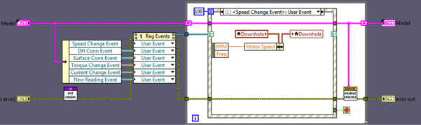
Figure 6 - LabVIEW View
All software architectures have weaknesses. Due to the global nature of all View Models, it is possible for a developer to access the model data of another module directly. This opens the architecture to race conditions and data corruption. Luckily, this is a development-time issue and can be resolved with proper training. Developers should practice never directly accessing the data model belonging to other modules.
Lastly, MVVM modules are inherently asynchronous and are never intended to act in synchronous operation. Adding synchronous operation between modules requires the use of blocking inter-process communication such as queues or notifiers. However, when creating synchronous operation between modules, code reusability is reduced as the modules become tightly coupled and unable to exist on their own.
Model/View/View-Model is no longer just a Windows architecture. Its LabVIEW implementation provides a light-weight, flexible, and re-usable architecture that can tackle a wide variety of projects.
Download our white paper, “Developing Efficient LabVIEW Projects using a Team-Based Approach” to learn more about different approaches to software architecture.